WEEK
NINE
OUTPUT DEVICES
Task for this week
Group Assignment
Measure the power consumption of an output deviceIndividual Assignment
Add an output device to a microcontroller board you've designed and program it to do somethingGroup Assignment
This week we have to measure power consumption of an output device. When we connect the component to the micro controller the value of volatage notchanged but the value of current change on the load. For output device We selected the I2c display. It reqiure 5V for the operation. Now when we
calculate power, we have to measure the current also. So we calculate the current for this display. After measuring the volatge and current we apply
the formula for power calculation.
Power=Volatge*current
Click here to know more about group assignment.
Individual Assignment-
This week is for the output devices. Output device are those device which shows the information. The information may be in text, light and
sound form. So for this assignment I have decided to design a new PCB with xiao RP2040 Microcontroller and I am planning to
test this microcontroller with led, servo motor, Matrix display relay and buzzer. I designed the board by taking the output devices pin so that we can connect
output device pin at particular place in the PCB boards.
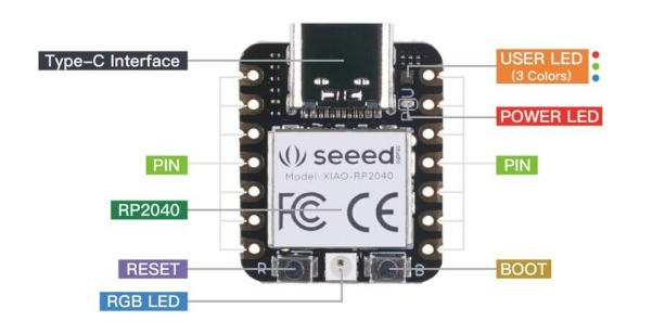
Xiao RP2040
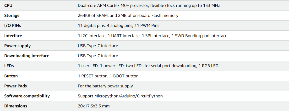
Xiao board belong to Raspberry family. It contaion Raspberry RP2040 chip. This chip have 246kb of SRAM and 2 mb of flash memory. It can run on upto133MHz. The size of this board is 20mm*17.5mm just equal to our thumb. Its small size make it uses in the mini project where low space are there.
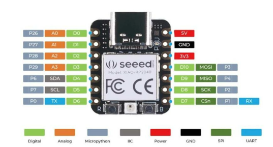
It consist a RGB light on it. It also have a reset and boot button. This board have 11 digital pins, 11 PWM pins, 1 I2C interface pins, 4 Analog pins
1 UART, 1 SPI, 1SWD pins. It easily support c,c++ and python. This board have type C pin for the serial data communication and power supply.
Reference
PCB Design
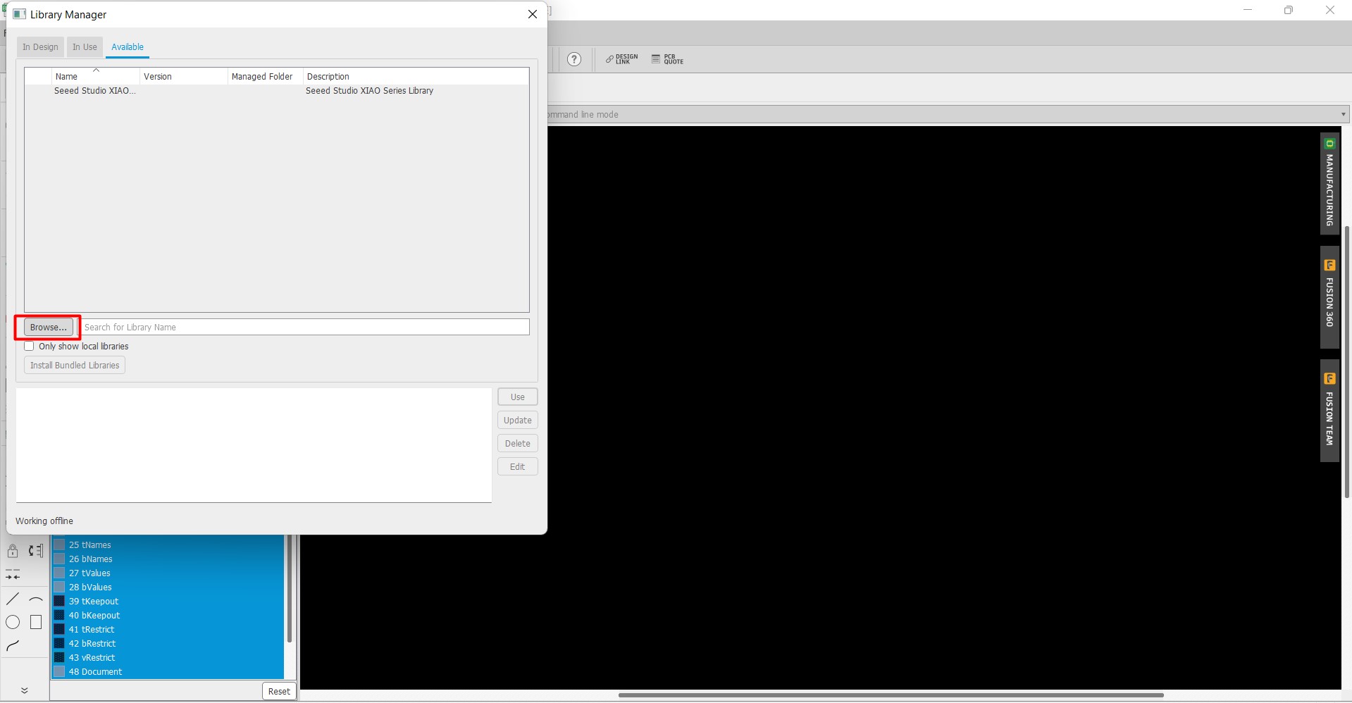
First of all I add the library of Xiao board in eagle. To add library, go to library option and open library manager. then Browse your file and select it andthen select use option.
click here to download eagle library.
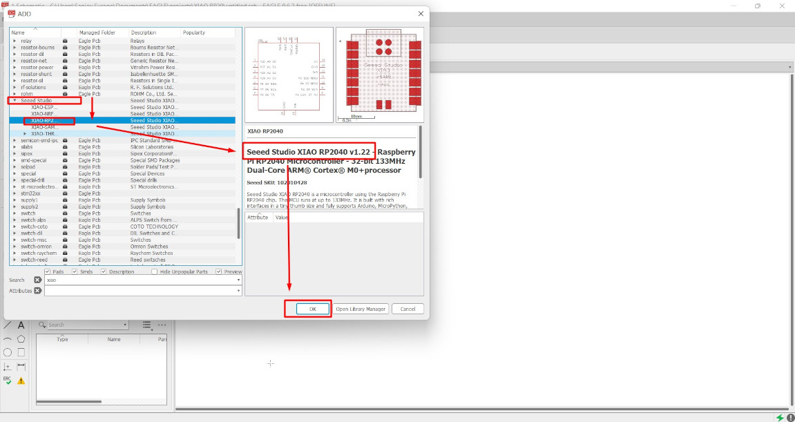
Now we have select the component by clicking on add part option and choose the component which we wantto add in our pcb board.
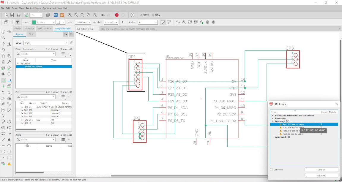
After that we connect the component and run electronic rule check(ERC). During ERC we found some unconnected component so we connect the component again.
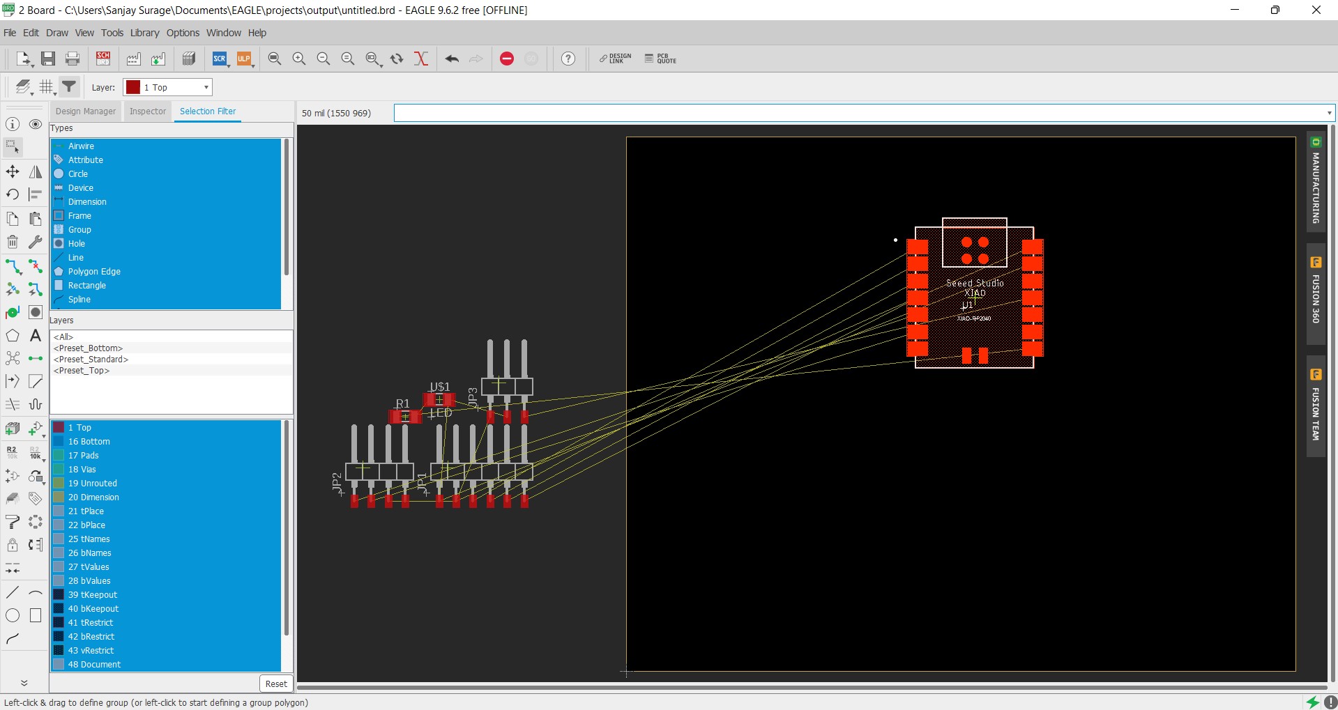
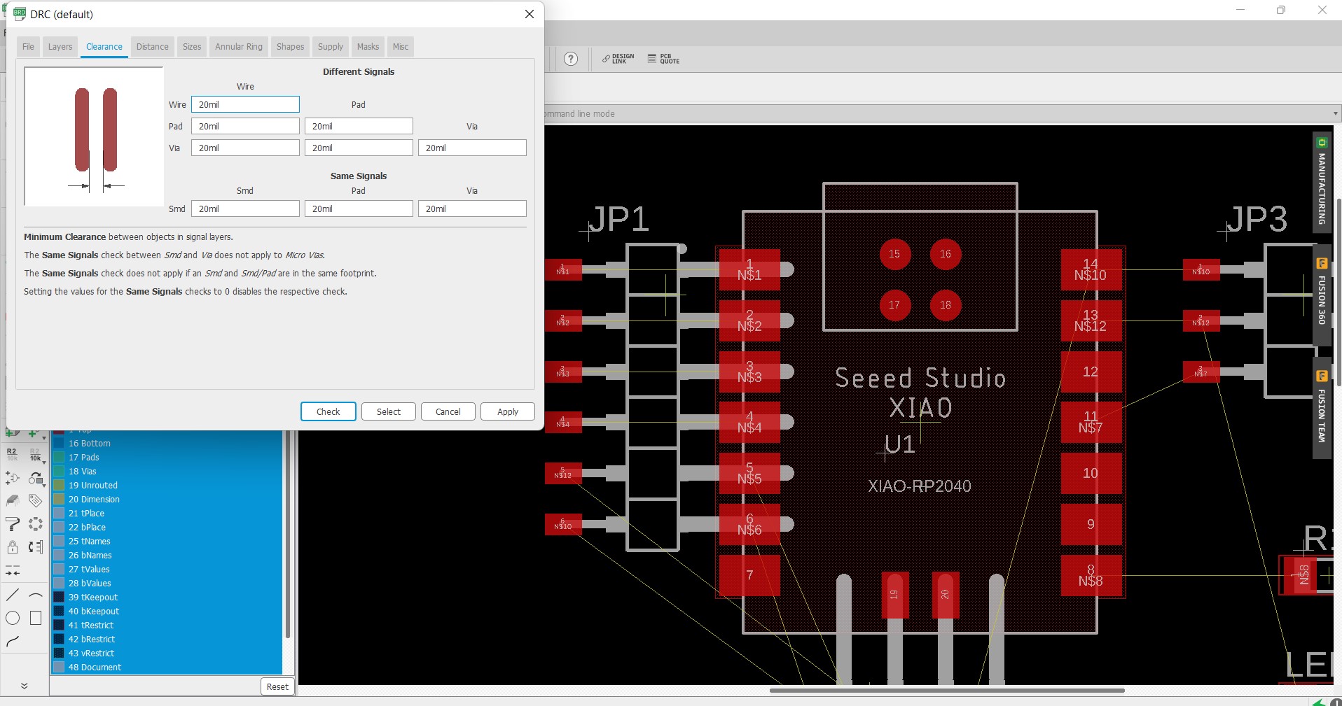
Now we switch the board from Schematic to board. We set the DRC (Design rule check) according to our tool diameter and current passing value .
Then we arrange all the compoenent in a particular manner and connect them by wireframe tool.
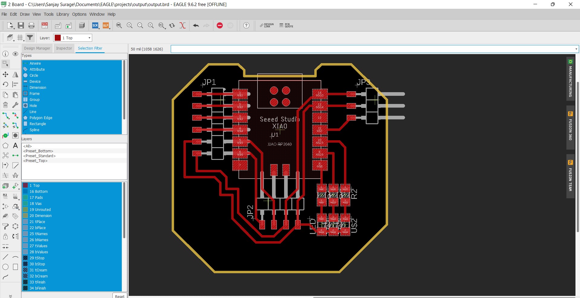
Then Export their PNG file for Milling and cutting operation.


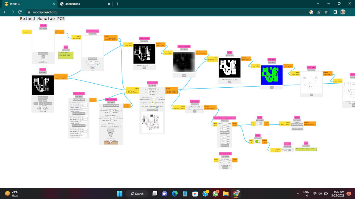
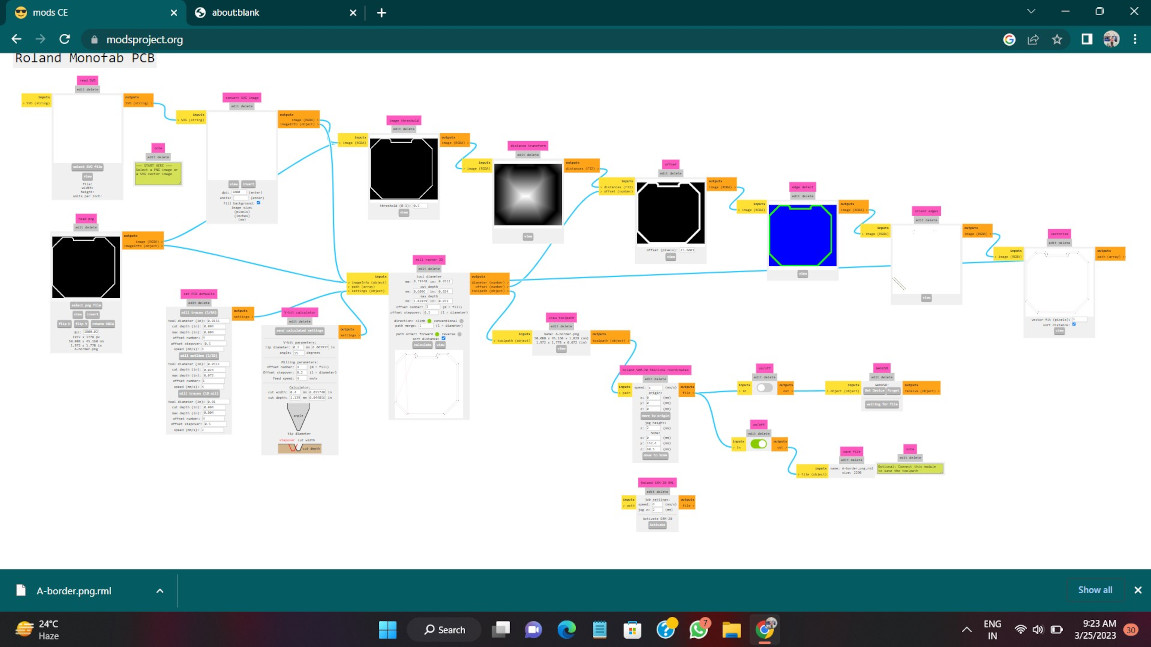
Now we use Mods CE platform for toolpath generating for our PCB Board. Select the file and then select 1/64 tool for milling operation and 1/32 tool for cutting
operation. Then make the machine origin 0 for for all three axis and calacute the data. A tool path file for the board is downloaded.
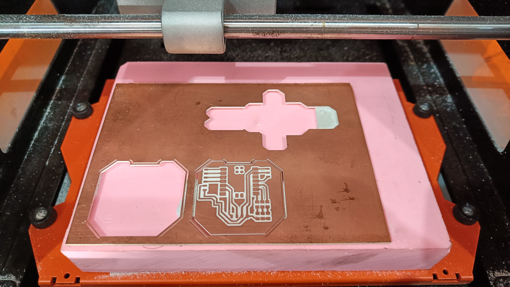
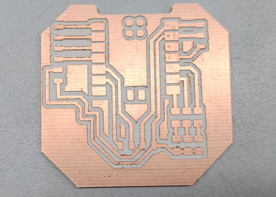
After tool path generation of the png file we mill the board by using SRM 20 machine .
NOTE: I am using FR4 board in this assignment due to unavailability of FR1 board in our lab.
Component Used
• Xiao RP2040 -1 nos• 6 pin female pin connector- 1 nos
• 4 pin female pin connector - 1 nos
• 3 pin female pin connector - 1 nos
• 1K resistor of 1206 package- 3 nos
• 1206 package LEDs(three color)- 3 Nos
Soldering Process
Then I soldered all the component properly. This time my soldering is not good enough.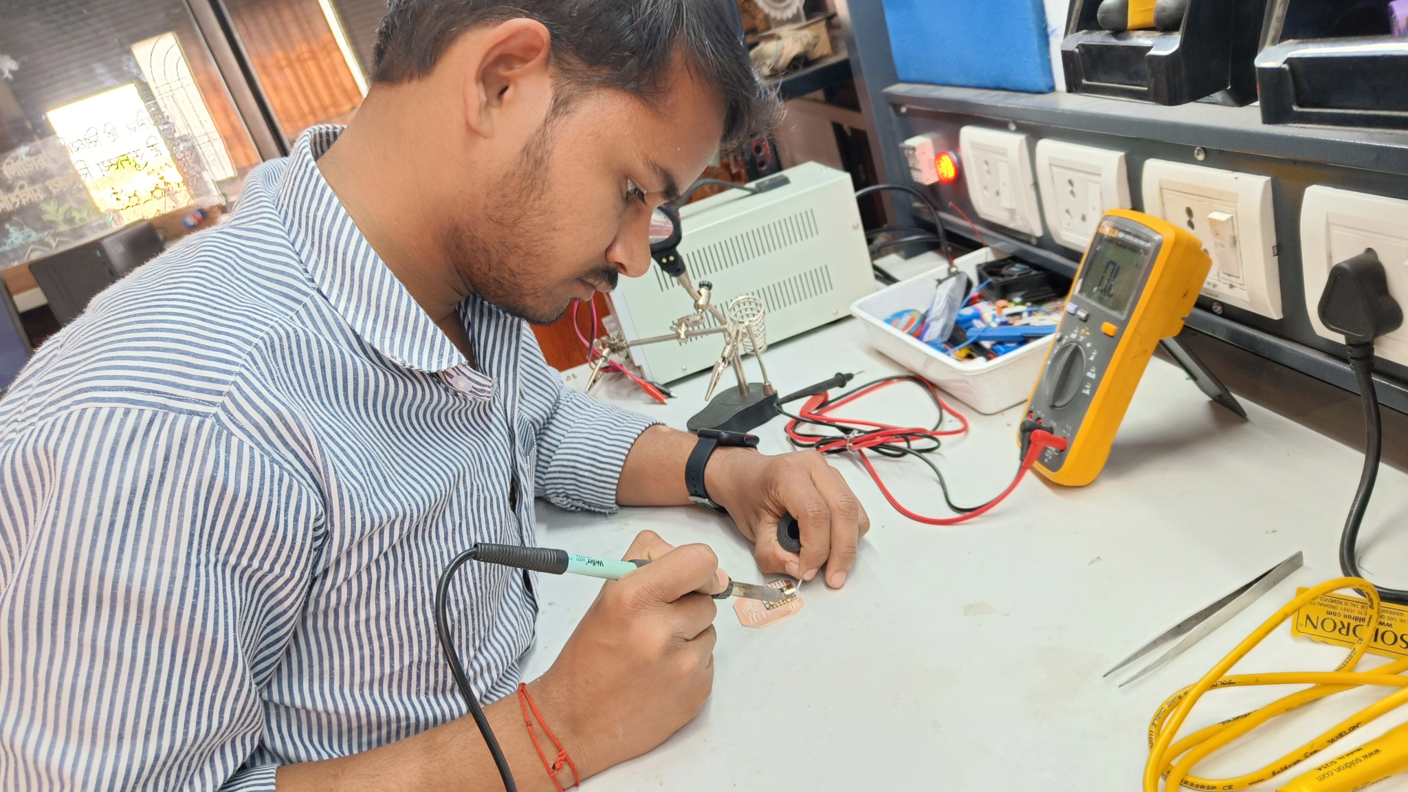
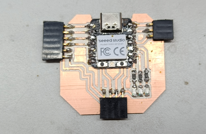
Final board -
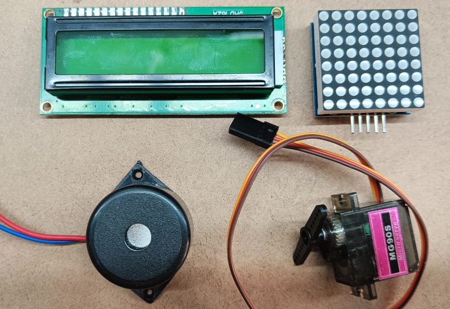
Output devices for this week
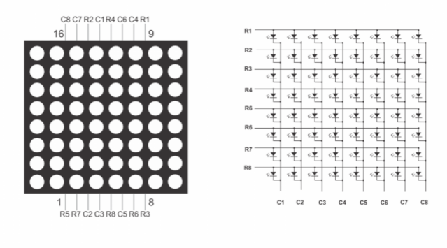
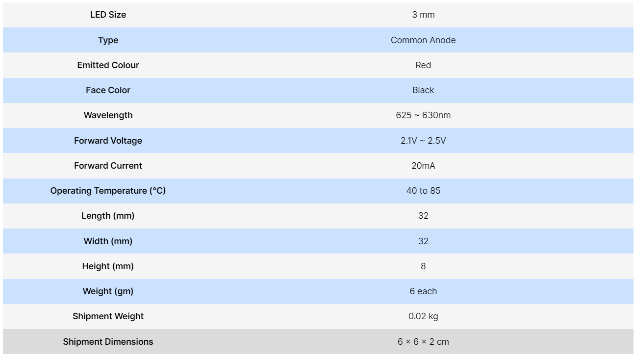
8*8 Matrix display
Matrix Display are used to make sign board and other text scrolling project . This board have total 64 leds in it. The 8 leds are present in the rowand 8 leds present in the column. The leds size is about to 3mm. This matrix module have total 16 pins by we can glow any led in the Display.
The interconenction between the led are can be seen by a picture below.
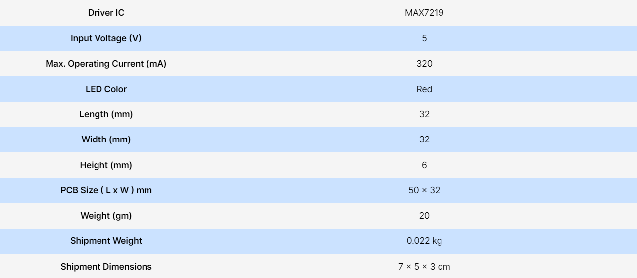
Now we have trouble to connect all this 16pins to microcontroller so for this we use a board which consisit MAX7219 driver chip which easily controll all this
64 leds. This IC also used for controlthe seven Segment display. This board have only 5 pins which we can easily connect it with microcontroller.
This pins are VCC, GND, DIN, CS, CLK .
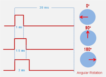
Servo Motor
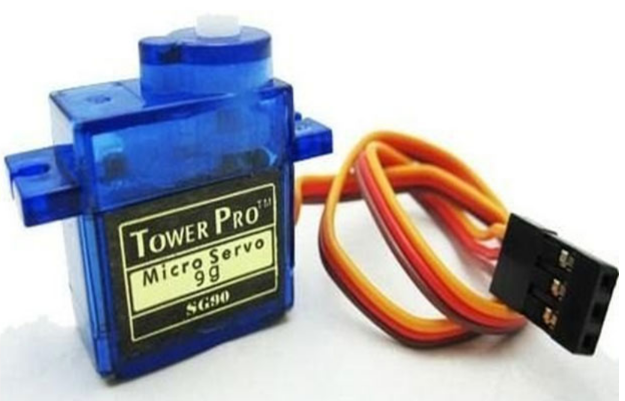
This motor have gears inside it by which the motor provide great torque.This motor is very accurate with its motion. It rotate with measurement
in angle. This motors are rated with kg/cm. for example if a servo has rating 2kg/cm means it can pull the weight of 2kg for about 1cm. It consist three contoller
system in it.
1.controlled device
2.output sensor
3.Feedback system
When we give a signal to the servo, the system check the value of signal and shaft started rotating. shaft of the motor connect with potentiometer. When shaft rotate
Potentiometer also rotate. when the potention meter value become equal to the Input signal value, the rotation of the shaft stoped. The servo motor consist three
pins- VCC, GND, Signal. We provide signal in PWM form .
Reference and purchase link From Robu.in
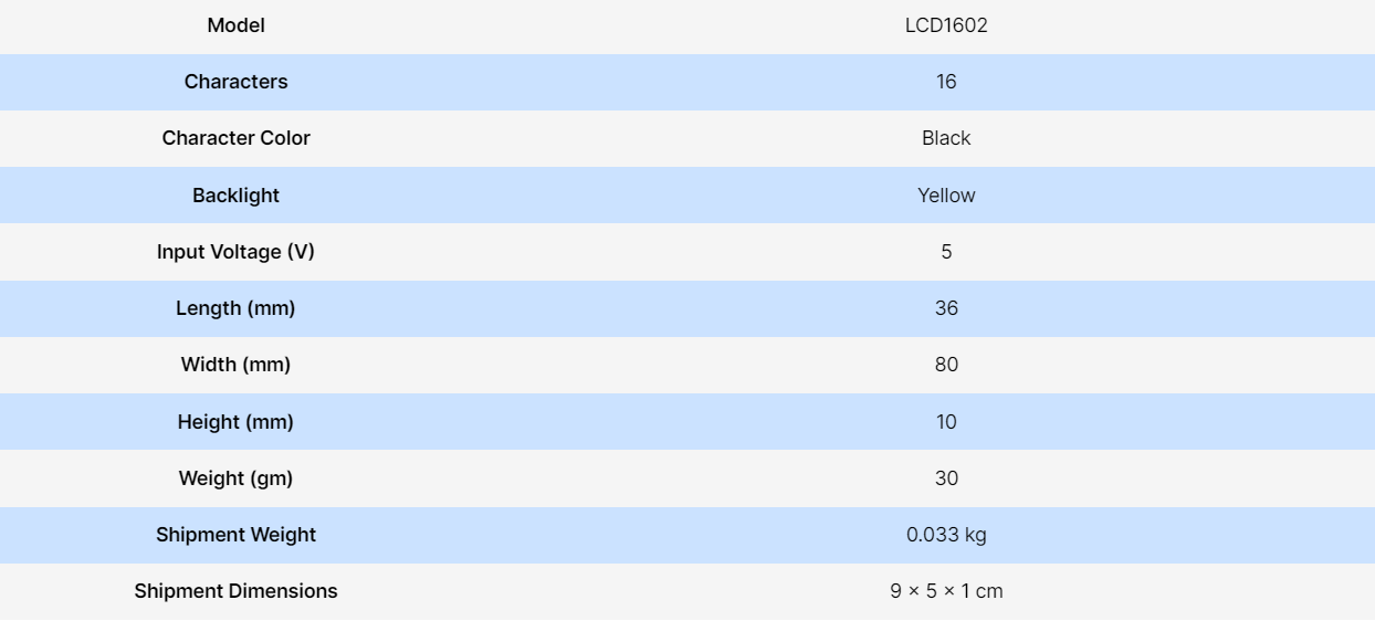
Liquid crystal I2c display-
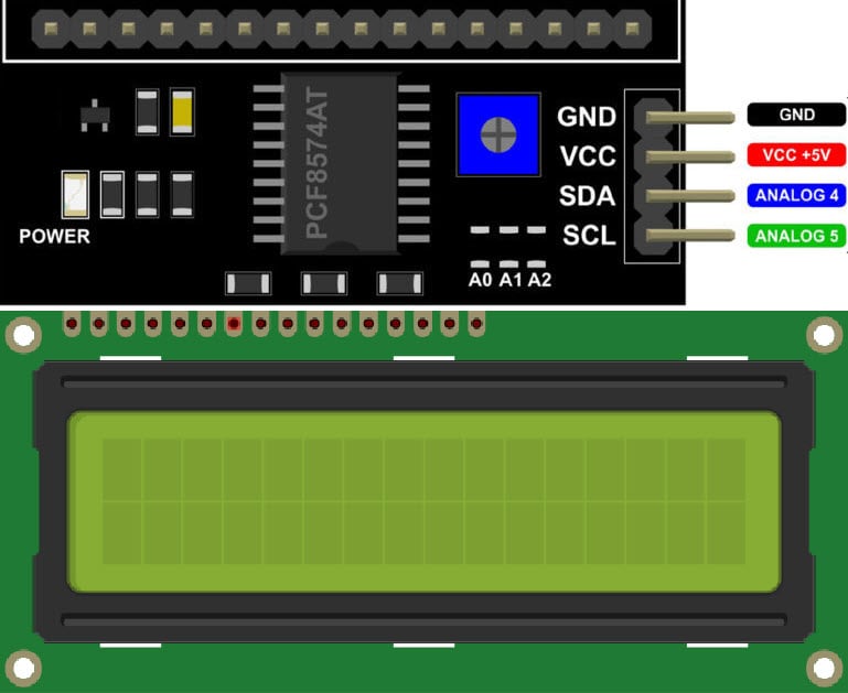
This is a liquid crystal display of 16 *2 row coloumn system. It is used to show any display parameter of text and number. It have yellow backlight.
It consist 16 pin on it but by connect I2c module there are only 4 pins are available for connect to the microcontroller. The I2c module
have 4 pins SDA (serial data ), SCL(serial Clock), GND, VCC. The SDA and SCL are Bidirectional pins and they connect on I2c pins of the microcontroller.
The data are send by SDA pin in the form of bit and the flow of bit control by the SCL pins. They required volatage of 5V for the operation.
It also have a potentiometer to adjust the text clarity on the display.
Reference and purchase link From Robu.in
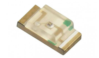
LED-
LED is a light emitting diode which emits light when we provide supply to it. This time I am using Three SMD LEDs in the board as a output device.we will connect this led with 1k resistor in it.
Buzzer
Buzzer is device which produce high frequency sound when we supply the power. This device are used to many alarm , warning and emergency systemThis device have many types like Piezoelectric , Electromagnetic, Mechanical and electromechanical.
1.Piezoelectric - In this technique , when we supply the power , the sound is produce by vibration of two metals.
2.Electromegnatic- In this sound is produced by the vibration of coil into magnetic field.
3.Mechanical - This also come in category of electromagnetic buzzer , it have same part like electromagnetic buzzer. The difference is that
the vibrating mechanism are set outside rather than inside.
4.Electromechanical - this type of buzzer have combined feature of Electromagnetic and mechanical.
Reference
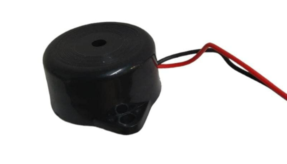
We are going to use Piezoelectric type buzzer which required 5-12V to operate and produce sound 95 DB. It have only two wire, one is positive
another is negative.
Xiao Board manager Installation
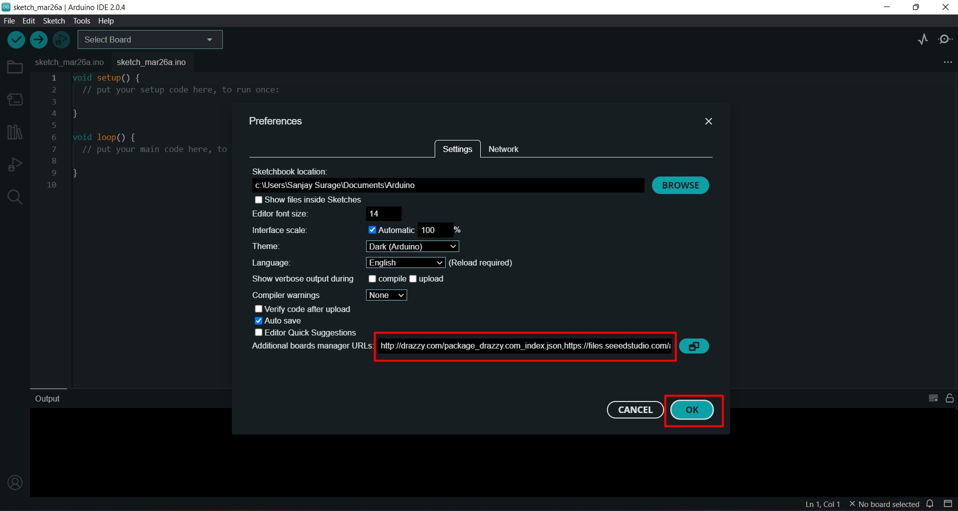
Now we have to add xiao board manager in the arduino ide. To add board follow this steps-Go to File >> preference >> past the board URL ehich is given below and click on ok.
URL- "https://github.com/earlephilhower/arduino-pico/releases/download/global/package_rp2040_index.json "
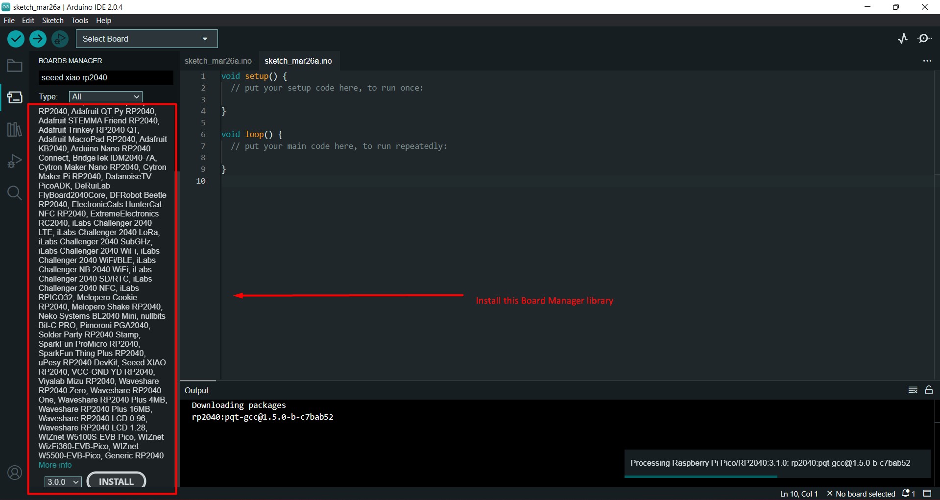
After that go to board manager serach the "xiao RP2040" and install it .
After that go to the tool section and select the Xiao RP2040 and port for it.
Board Pin Configuration
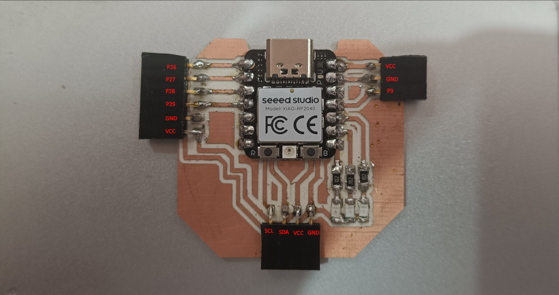
Testing with Output Devices
Matrix Display
Matrix display have total 5 pins CLK, GND, DIN, VCC, CS.Connection diagram-
DATAIN- P26
CLK- P27
CS- P28
Code-
Now we have to add the library for the matrix display, so to add library follow the steps-
Go to sketch >> Include library >> add Zip file >> then select zip file
you can download the zip file library of matrix from here
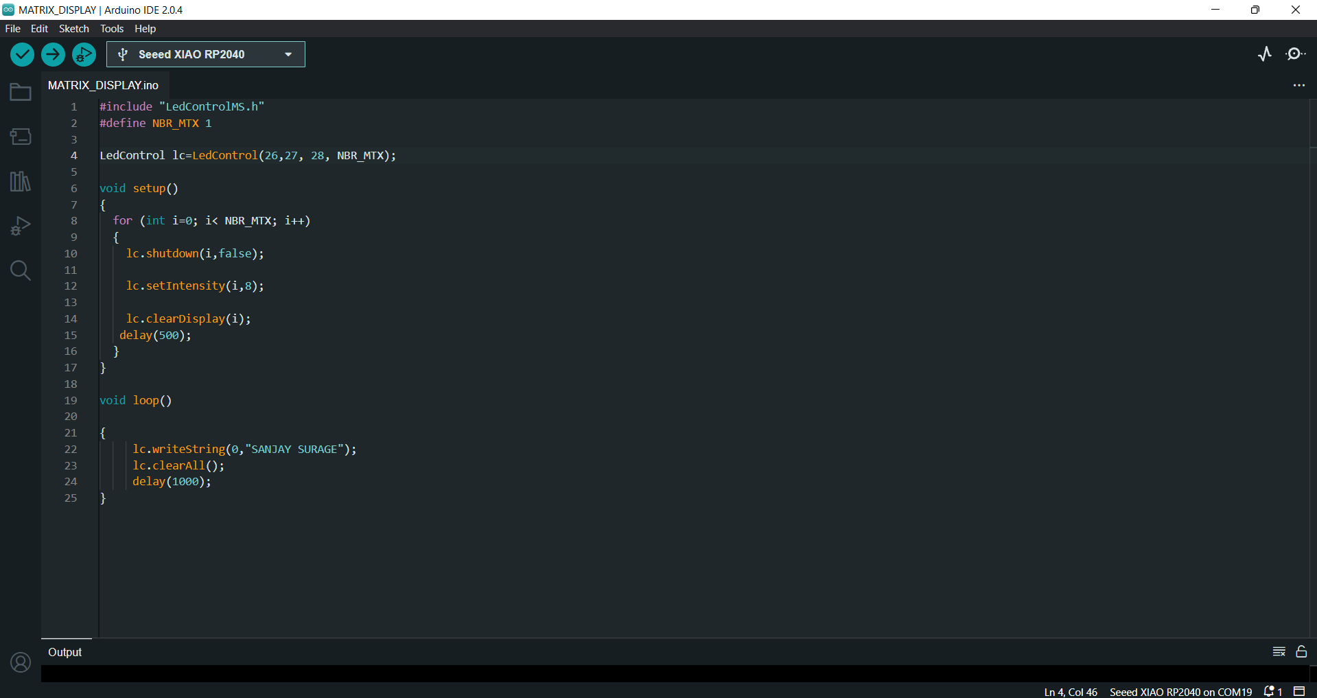
Download FileAfter that I am trying the code for the text blink. Firstly I defined the pin for the display in the code then I define the no. Matrix display
used. In my case I am taken 1 display so I set the one in NBR matrix. After that a foor loop define in void setup. This for loop is for the print the text
in number of display. Then we set the itensity or brightness for the display. Then we define text for print in void loop .So I write my name in Write string.
Code
Result-
Servo Motor
Servo motor have three pins VCC, GND and Signal-connect -
Signal PIN- P3
GND-GND
VCC-VCC
Code-
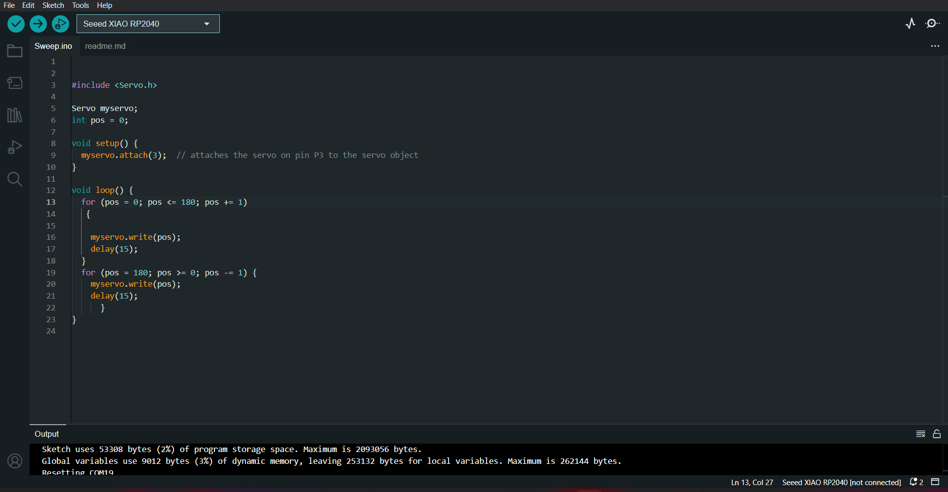
For the servo motor we have to install it library first. The After installation I tried to rotate the servo in 180 degree. So I definea myservo variable. Then I define the pin no 3 for it. Then I define its condtion for its position. So for this I take for loop and run it
from 0 to 180 degree. Then define the position in myservo .
Result
I2c Display
I2C display have 4 pins SDA, SCL, VCC, GNDConnect-
SDA-SDA
SCL-SCL
VCC-VCC
GND-GND
Code
Firstly install the library of I2c display. Then define its address in code. After that set the backlight function. Then Set the cursor value and print the text.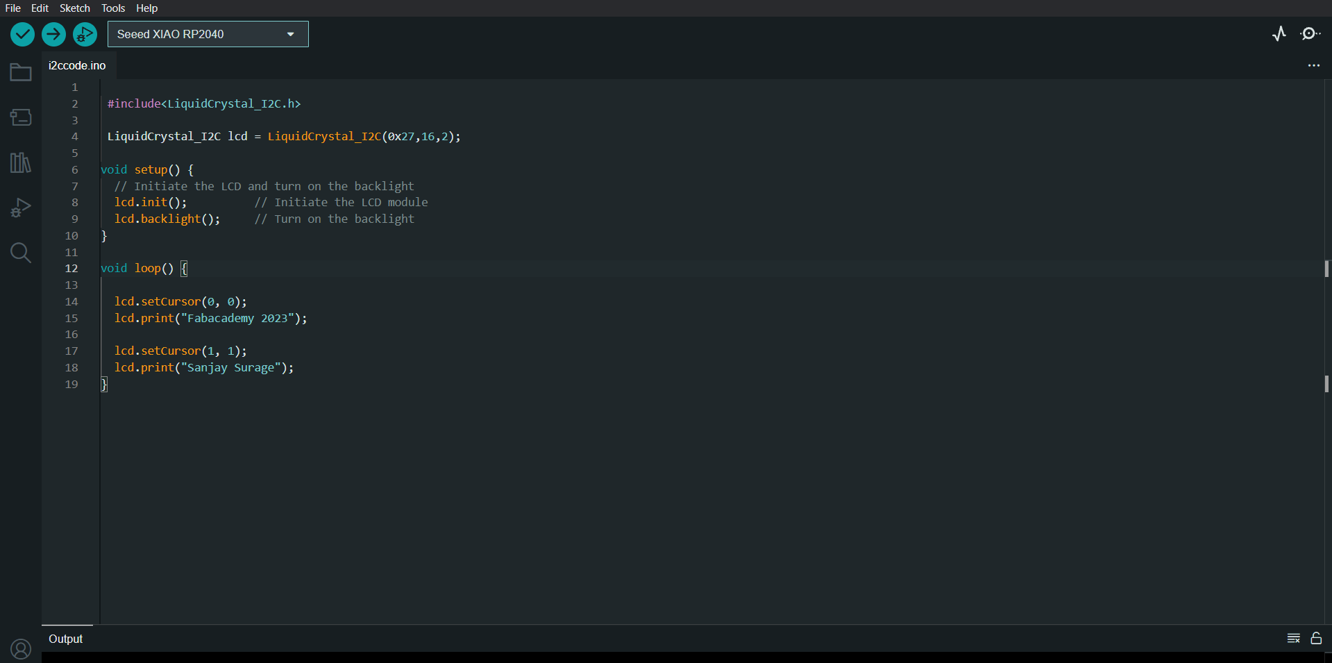
Result
Leds
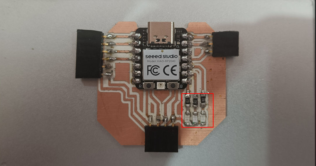
I connect the three leds inside the board. This leds are connect to P1, P2 and P4 with 1k resistor
code-
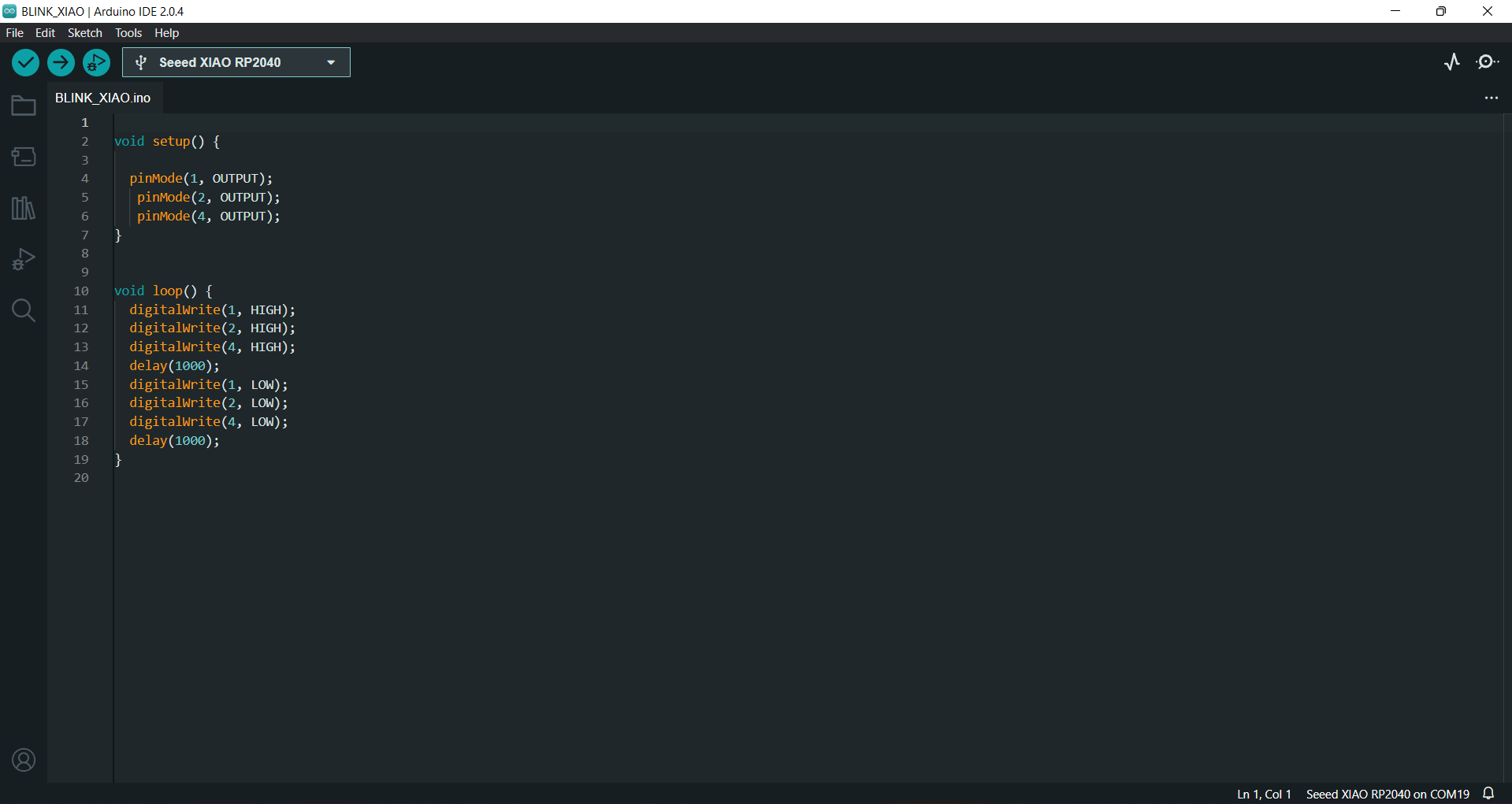
Result
Buzzer
I also connect buzzer with this board and programme it to on and off for 1 sec. I connect the postive wire to P3 and negative wire to GNDCode-
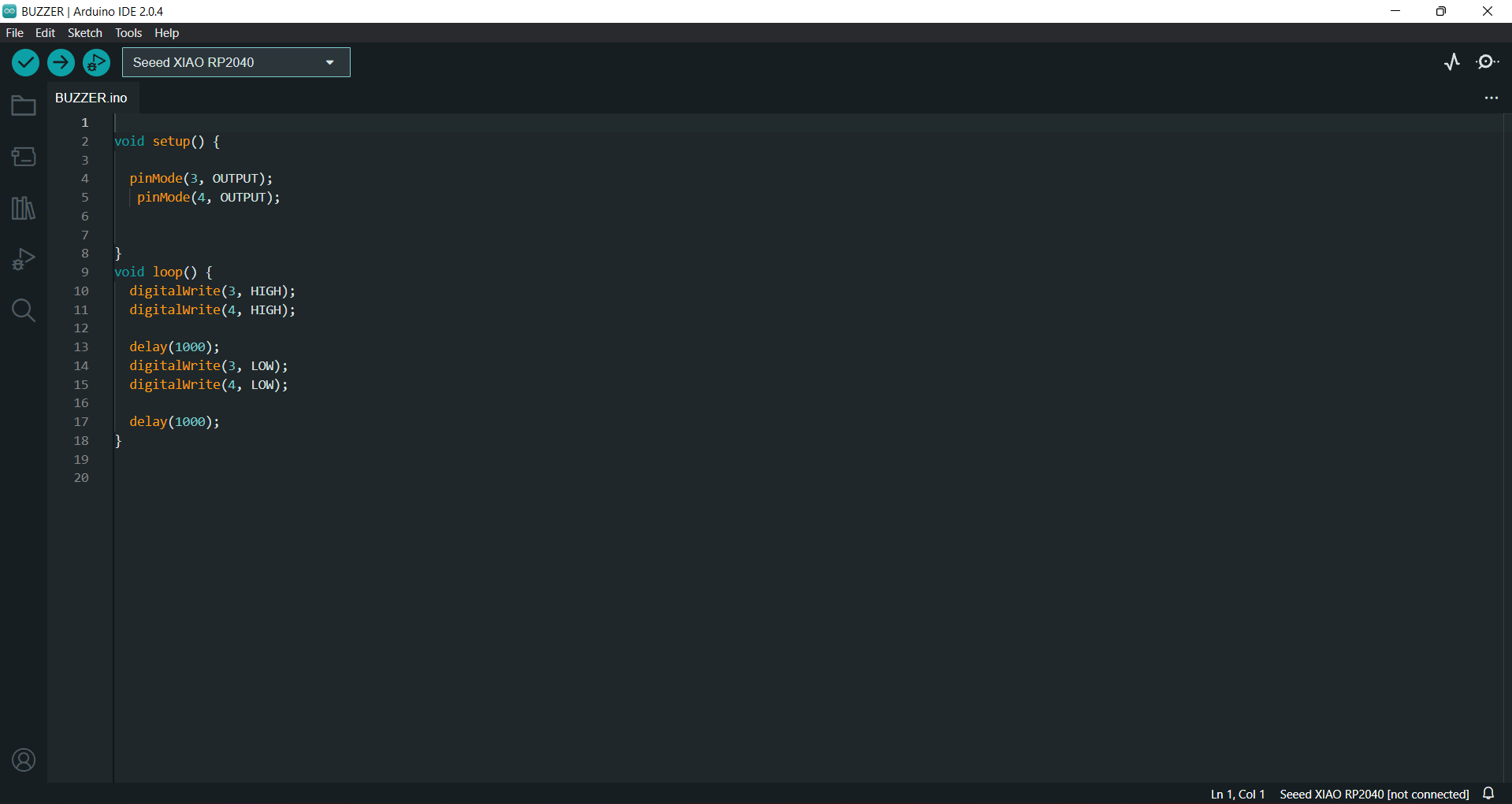
Result
Learning outcomes
-I learned about power consumption for output device.-I learned about the Xiao board
-I designed a new PCB with Xiao RP2040 on Eagle.
-I learned about different type of output devices
-I learned about the wiring connection and programe my PCB for Output devices
Download the all original file
Download FileClick here to know more about group assignment.